PC-Based Ultrasonic Test System Basics
Overview
Several PC-based and external components make up each ultrasonic test system. Each of these components has a unique set of features and considerations. Some considerations are limited to the component itself while others depend on the various components in the system. This document describes each component in the system, some of the features/issues that you should consider, and how these components can be put together to build a custom, flexible ultrasonic test system.
Assembling an Ultrasonic Test System
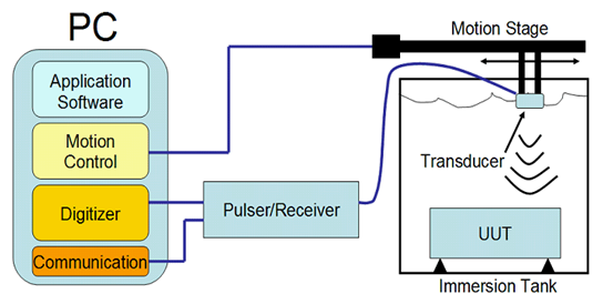
Ultrasonic test systems can take several forms, but the most common for automated test is immersion testing. To achieve effective acoustical impedance matching between the couplant and the UUT and free range over the entire surface of the UUT, many test systems use an immersion tank filled with water.

These test systems use one or more ultrasonic transducers, which are moved over the surface of the unit under test (UUT). As the transducer is moved over the surface, it is pulsed and receives echoes from various surfaces. This process is repeated many times a second — sometimes more than 50,000 times per second (>50 kHz). There are several pieces of the test system that must work together to get expected results. The following list includes the steps, and the accompanying hardware and software pieces, required to get one pulse and the subsequent echoes:
Application software – The user interacts with the application software to set up the test and presentation parameters.
1. Motion control – The ultrasonic transducer is moved over the appropriate area of the UUT.
2. Communication – The pulser/receiver operation parameters, such as pulse energy, pulse damping, and bandpass filtering, are set. The communication path is typically RS232 or USB.
3. Pulser/receiver – This device generates the high-voltage pulse that is required by the ultrasonic transducer.
4. Ultrasonic transducer – The transducer is pulsed, sending out an ultrasonic wave. The subsequent echoes generate a voltage in the transducer, which is sent back to the pulser/receiver.
5. Pulser/receiver – The analog signal from the ultrasonic transducer is amplified and filtered before it is sent back to the digitizer within the PC.
6. Digitizer – The waveform sent from the pulser/receiver is converted from voltage to bits using an analog-to-digital converter.
7. Application software – Data from the digitizer is processed, analyzed, and presented according to the user-defined parameters.
If you have multiple transducers that are combined with one digitizer/pulser/receiver combination, you must use switches.
Several hardware and software components must interact effectively for even the simplest ultrasonic test system to work properly. When assembling your custom ultrasonic test system, you have several factors to consider for each component of the system, including how well the components interact with one another. The ultrasonic transducer section describes each component of the test system in detail as well as the important features required for ultrasonic testing.
Pulser/Receiver
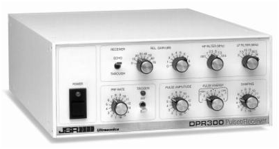
These devices provide the high-voltage pulse required by the ultrasonic transducer as well as signal conditioning before the analog signal is passed to the digitizer. For use within an automated test system, the pulser/receiver should be computer programmable via a standard PC bus such as RS232 or USB. The devices are typically programmed one time at the beginning of the test to set the pulse voltage level, pulse repetition frequency, damping, band pass filtering settings, and several other parameters. After these parameters are set, these devices are passive and do not send any information back to the PC during operation.
The motion controller, digitizer, and pulser/receiver must operate as one tightly timed unit during the test to ensure accuracy of results and brevity of test time. The pulser/receiver can act as the master timebase of the system or can act as a slave to the digitizer or motion controller. In the applications where motion control is implemented, it is typically the slowest part of the system and, for that reason, acts as the master timebase.

PC-Controlled Pulser/Receiver – Courtesy of Imaginant
深圳市海森纳电子有限公司 版权所有 Copyright © 2017 All Rights Reserved 备案号:粤ICP备07051703号